Acoustic Radiation Force Impulse (ARFI) Imaging
Background
Radiation force is a phenomenon in wave motion where part of the energy of the traveling wave is converted into momentum after experiencing absorption, scattering, or reflection. The first description of radiation force can be traced back to Johannes Kepler in the 17th century who suggested that energy from solar rays was responsible for deflecting comet tails. Almost two centuries later, radiation force was found to be associated with acoustic waves as well, and emerged as a unique field of study in 1902 after the extensive work of Lord Rayleigh. However, it wasn’t until 1990, when ultrasound was already an established field, that acoustic radiation force (ARF) was proposed to be utilized as an extrinsic excitation source for elasticity-based medical imaging techniques by Sugimoto et al. Over the last few decades, a multitude of ARF elasticity imaging methods have been developed and commercialized for clinical adoption. Specifically, in our lab one of main focuses is ARFI imaging, which utilizes impulsive ARF excitations to generate qualitative images of mechanical stiffness as described below.
ARFI Imaging
In acoustic radiation force impulse (ARFI) imaging a single ultrasound transducer is used to both induce and monitor on–axis deformation in order to generate qualitative images of tissue stiffness. At a single lateral location, an ARFI pulse sequence consists of three pulse types: 1) reference pulses that precede the ARF burst and are used as a baseline for tissue position, 2) pushing (ARF) pulse that consist of a high-intensity impulse to displace the tissue, and 3) tracking pulses that monitor the tissue dynamics following the ARF burst. Tissue displacement is measured using correlation or phase-shift estimation techniques on raw RF data from the reference and tracking pulses. The pulse sequence and motion estimation is repeated at a number of lateral positions across the imaging field of view (FOV) to build up a 3D data set consisting of tissue displacement as a function of axial position, lateral position, and time. From this data, 2D parametric images can be rendered by extracting various features from displacement vs. time curves at a given spatial location, such as peak displacement (PD) and time to 67% recovery from the peak (RT).
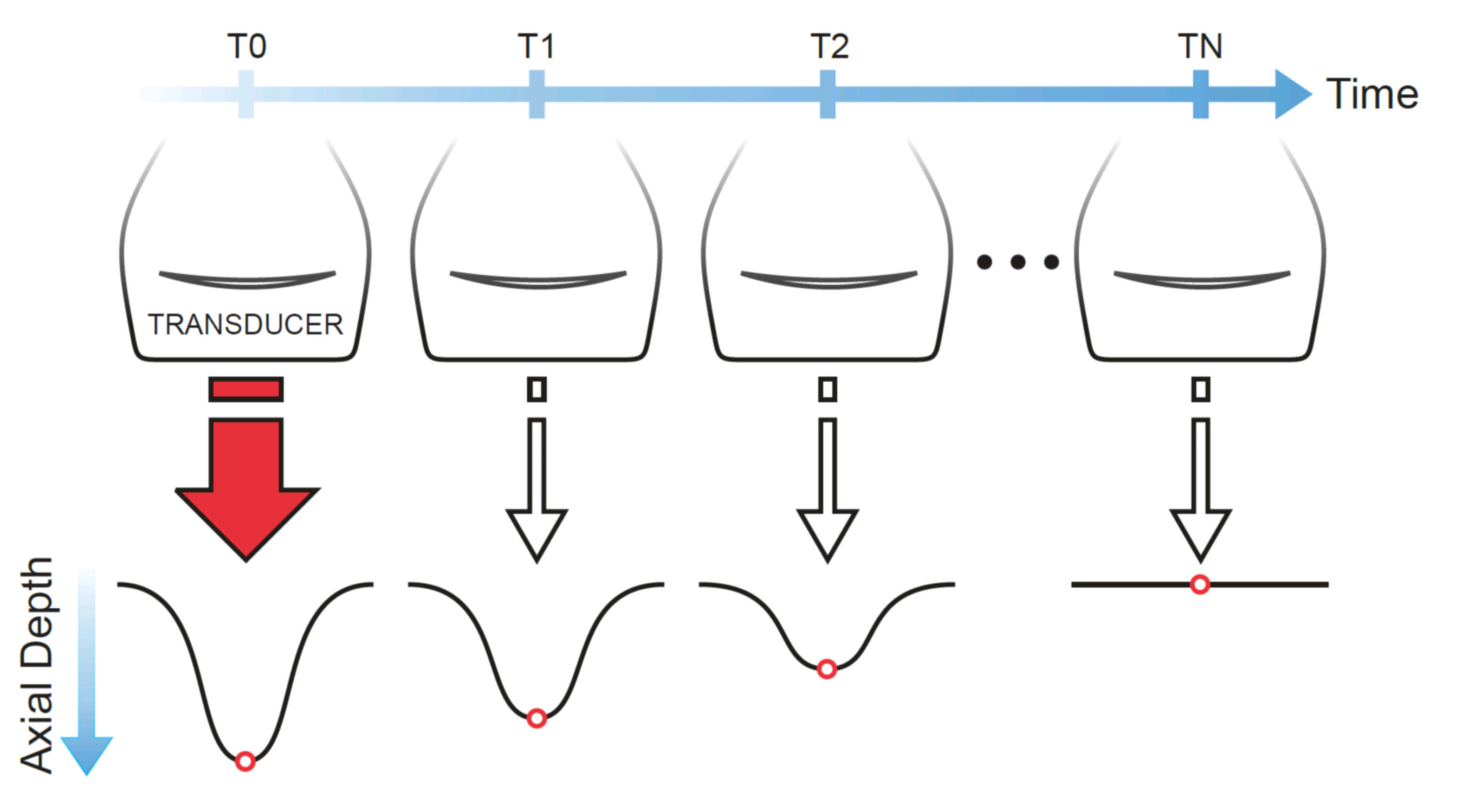 Illustration showing ARFI acquisition.
Displacements induced in ARFI are typically small (1-10 µm) and the tissue fully recovers to its baseline position quickly (4-6 ms). Areas of higher displacement are indicative of mechanically softer regions in the tissue, while smaller displacements indicate stiffer regions. Calculating quantitative tissue modulus from ARFI-measured displacements is currently not feasible due to uncertainties in the exact magnitude of force delivered to the tissue, which is materially-dependent. However, novel methods that fit ARFI-derived displacement profiles to biomechanical models, as done in viscoelastic response (VisR) imaging, may be capable of determining quantitative parameters in the future. ARFI has been commercialized on the Siemens ACUSON S2000 and S3000 scanners under the brand name Virtual TouchTM Imaging (VTI).
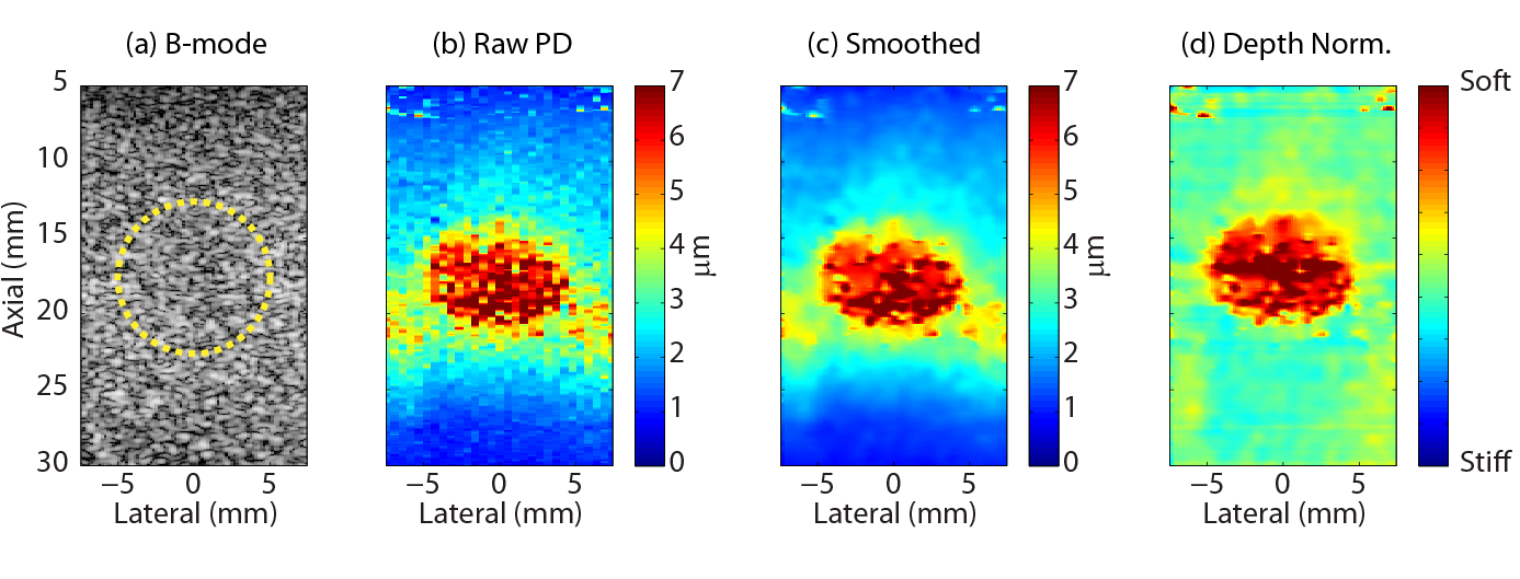 Example of B-mode and ARFI images in a tissue mimicking phantom with a soft spherical inclusion.
Experimental Validation of ARF
In collaboration with the Dayton lab at UNC, we experimentally validated ARF in an optically translucent tissue mimicking phantom using a high-speed camera imaging at 150 kHz. We embedded small microparticles (10 µm diameter beads) in the phantom to serve as optical tracers, and confocally aligned our ultrasound system with a microscope for simultaneous optical and acoustic tracking of ARF dynamics.
The movie below shows the image frames captured by the high speed camera as well as the motion tracked both by the camera (blue line) and the ultrasound system (red dots). The pulse repetition frequency of the ultrasound system was ~11 kHz. The acoustic intensity of the ARF pulse was increased in this experiment to exaggerate displacement (which reaches a peak of around 40 µm). Notice that the ultrasound tracking underestimates the true displacement (as measured by the optical setup). This is the result of tissue shearing within the imaging point spread function, and a known limitation of ARFI imaging. More details of this work can be found in our publication Czernuszewicz et al. 2013 (PMID: 23858054).
Optical (blue lines) and acoustic (red dots) tracking of an ARF impulse.